Light Pipe Design Guide
What Are Light Pipes?
How Do Light Pipes Work?
A light pipe is placed very close to an LED light source on one end of a PCB board. Its optical-grade materials help carry the rays of light to the desired destination, typically at the user interface of a device.
Light pipes transmit roughly 80 to 90 percent of the light from the LED source, depending on design and spacing. The closer the light pipes are to the LED(s), the more efficiently they can transfer light.
Of course, the light pipe(s) used will need to be rated for the same amount of heat that is produced by the LED or light source, so that must be a design consideration as well that can dictate the minimum allowable distance between the light pipe and the light source.
Why Use Light Pipes?
Depending on the equipment and the design of the user interface of a device, a product can require more than one and up to many indicators. For designs that require multiple indicators, light pipes are an ideal solution due to their low cost, excellent visual communication, and design flexibility.
Light pipes offer many advantages in efficiently transporting light in a defined area. But they can also transport the energy of electromagnetic waves, such as UV, infrared (IR), visual light, laser, and other types.

Illuminated Component Terminology
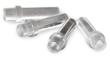
Light pipe - the term “light pipe” can also be called a “light guide” or “light tube.” To make things more confusing, they’re sometimes called “litepipes”, too. A light pipe is a rod made of optical acrylic or polycarbonate that transmits light from a light source, typically an LED, at the circuit board to the panel of the device. These light pipes are ideal for carrying the light in a small space, like a status indicator or control panel.
Light diffuser - light diffusers are used to spread light from an LED source over a defined area but also reduce the brightness of the light it transmits. Therefore, light diffusers are typically made of opaque materials. Light diffusers can be used in conjunction with light pipes or light guides. They also increase the viewing angle and are ideal for soft illumination of defined areas.
For this guide, we will be focusing on the fundamentals of LED light pipes, or litepipes, if you prefer that spelling.

LED Light Pipe Design Benefits
We touched on how beneficial light pipes can be — yet we can’t mention it enough. They deliver a host of benefits for designers and OEMs, such as:
Greater flexibility and control over - by adjusting the length, angle, and spacing, designers can get the exact visual indication and uniform light visibility they desire with the right light pipe design.
Minimized light leaks - when excess light shines through a device without illuminating the indicator properly, it leads to wasted light and provides a poor user experience in the final device. Selecting the right light pipe and optimal placement between the LED and panel delivers optimal illumination without losing light.
Easy installation - no matter the type of light pipe, the installation can be literally a snap with a snap-fit or press-fit light pipe.
Production efficiencies - when a device has multiple panel mount indicators (PMIs), the production costs can really add up. Light pipes are a great alternative that brings down the cost without skimping on reliability, design flexibility, or visual indication.
Easily customizable solutions - light simulations and ray tracing with advanced software help design teams develop the ideal indication solution that can achieve all of the manufacturer’s goals
Reliable, uniform performance - when combined with LEDs, light pipes of various lengths deliver a consistent and uniform illumination that can last the life of the device
ESD protection - light pipes can prevent electrostatic discharge that can damage the device by isolating the PCB or circuit board from the user interface
Light Pipe Characteristics & Design Guidelines
From one end to the other, there are several physical features of a light pipe that can impact performance and visibility.
At one end, you have the input, or where the LED fits inside the light pipe. On the other hand, you have the output or exit surface, where the light travels to the indicator light or user interface.
The geometry or shape of the light pipe itself is another variable. The shapes and materials selected are just a few factors that can determine how much light makes it to the end where the interface is located.
As a general rule, light pipes include the following attributes:
- Rounded corners - leveraging rounded edges inside the light pipe minimizes the amount of light that can escape before shining outside of the exit surface. A minimum radius of 0.5mm is recommended.
- Smooth, flat, or concave contoured surface - whatever matches the surface of the LED needs to be happening on the interior of the light pipe on the side where the LED is inserted (the input surface).
- Diffused exit surface - using a diffused surface where the light is visible at the exit will provide a uniform illuminated surface.
- Smooth, mirrored surface - to avoid light loss, a smooth or mirrored surface can be added to the light pipe’s exterior.
- Light-reflecting paint - for extra credit (and brightness), an optional coat of paint can be applied to the outside of the light pipe to aid in amplifying the light.

Light Pipes Vary in More than Just Color
Like with any new product design, the decisions made early in the process can shape some of the constraints that must be accommodated later in the process, from the size of the PCB to the amount of space on a panel. These decisions may not seem like that big a deal, but when light indication or user interface decisions are made early-on, the manufacturers and ultimately the end users win.
Light pipes are available in a variety of styles and can suit a host of LED mounting options.
To really maximize efficiencies in your product design, you need to know the pros and cons of the different types of light pipes.
They typically fall into two major categories: rigid and flexible.
Rigid Light Pipe Design Guidelines
Rigid light pipes are meant to be used in applications where the light doesn’t need to bend around a corner or angle. Therefore, these do not bend like flexible light pipes. They’re made of polycarbonate rods that transfer light from the PCB to the user interface.
Rigid light pipes are meant to be used in devices where the light only needs to travel a short distance from the PCB and panel, compared to flexible light pipes that transmit light longer distances... Although rigid light pipes do not bend themselves, they can still move light around right angles and tight corners.
Pros of rigid light pipes:
- Ideal for vertical or right-angle orientation
- Great for board-mount, press-fit, and surface-mount LEDs
- Bend light around a fixed corner
- Available in right angle, 1-position, 2-position, and 3-position
Cons of rigid light pipes:
- Designed to transmit light short distances
- Length cannot exceed:
- Press fit: 1.20”
- Custom design: 1.5”
- Standard design: 2”
One Additional Design Consideration for Rigid Light Pipes — Face Shape
The surface, or face, of a rigid light pipe is the acrylic or plastic piece that is visible to the end-user through the panel. These exterior surfaces are more important than they seem, as various properties can improve the performance of the light pipe.
Working environment, application, device design, and even light pipe length and shape should dictate which face shape would be ideal for a specific product. For example:
- Longer light pipes perform best with smooth light pipe faces or surfaces.
- Scattered or frosted textures, like a Fresnel lens, help diffuse or soften the light.
Common shapes for rigid light pipe faces include:
- Dome - provides the widest viewing angle and best visibility from different working positions.
- Semi-Dome - splits the difference between dome and flat shapes, delivering a diffused light output while maintaining a wide viewing angle.
- Flat - in applications where rays must travel longer distances through the light pipe, a flat face is the perfect solution. Additional elements, such as a Fresnel design, can help concentrate the beam.
Light modeling is essential to find the ideal specifications for the desired output.
To accommodate a range of applications and needs, VCC provides standard and custom rigid light pipes with dome, semi-dome, and Fresnel lenses.

Flexible Light Pipe Design Guidelines
Flexible light pipes are the exact opposite of rigid light pipes. They are made of a polycarbonate fiber that is designed to be extremely flexible. These bendable properties make it possible to transmit light around corners and tight spaces without losing much energy.
An ideal solution for a range of applications, flexible light pipes attach to the PCB and carry the light from board-mounted LEDs to the control panel while remaining secure and providing ESD protection.
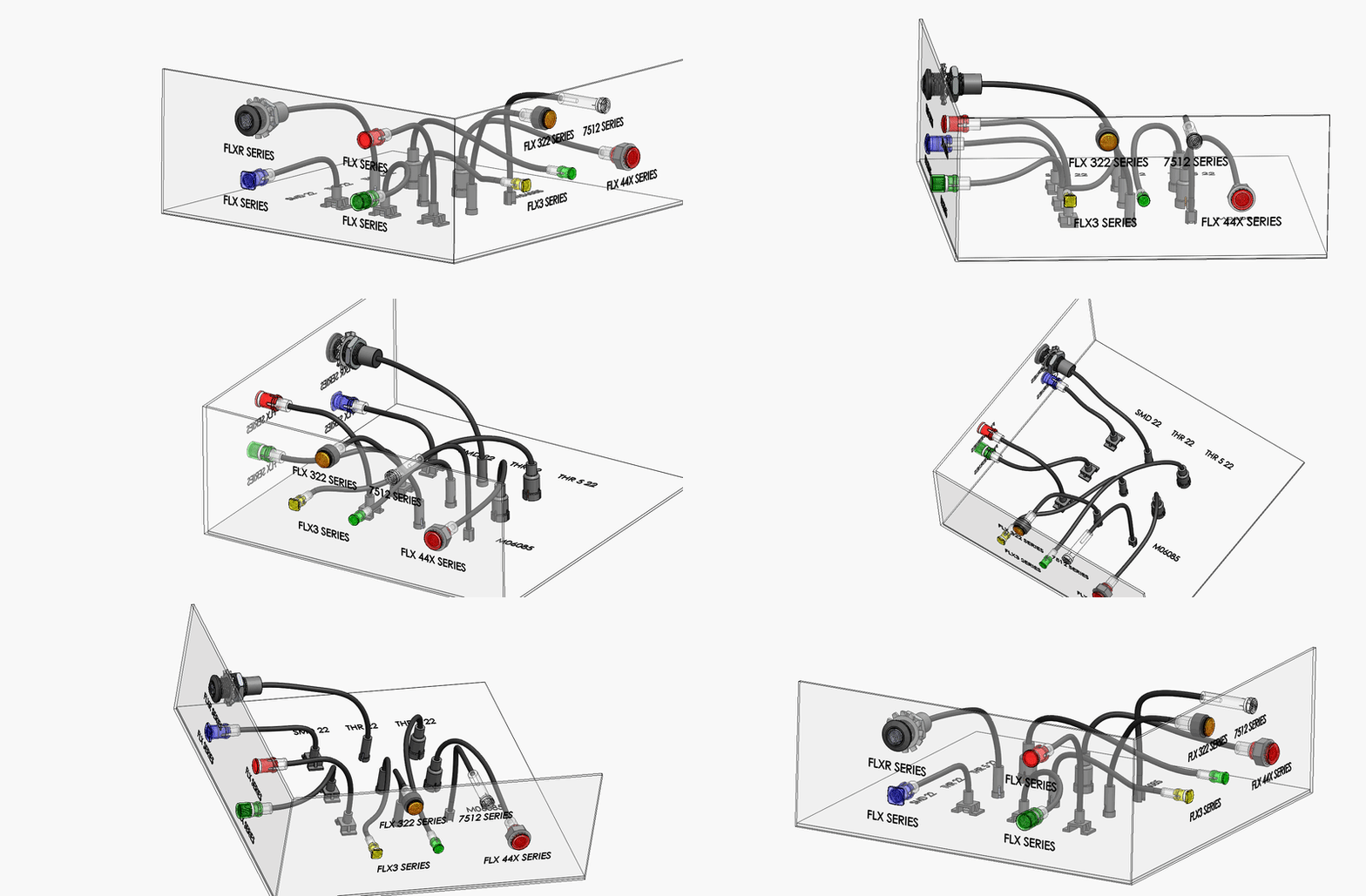
Pros of flexible light pipes:
- Carry light around curves
- Carry light around tight spaces
- Carry light longer distances
- Can bend up to 30 degrees
- Provide greater control over light optics
- Greater design flexibility
Cons of flexible light pipes:
- Typically cost slightly more than rigid light pipes
- No length limits per se, but the longer the light needs to travel, the more will be lost along the way
- An accessory is required to keep the flexible light pipe end close to the light source
Light pipes can be made with glass as well as a variety of synthetic materials with their own pros and cons.
The two most popular materials by far are optical acrylic and polycarbonate. Both of these materials are lightweight yet durable. They also possess the optical properties manufacturers require for a variety of applications.
Acrylic Light Pipes
Compared to polycarbonate, acrylic is hands down superior when it comes to optical properties. It’s easy to mold, naturally UV stable for indoor use, and transmits light better than any plastic material available.
So why wouldn’t you always use acrylic as your go-to light pipe material? There may be instances where you need a more durable light pipe that still performs well but also provides more resistance to heat. That’s where polycarbonate comes in.
Polycarbonate Light Pipes
Polycarbonate light pipes provide outstanding light transmission while being more suitable for higher-temp operations. Polycarbonate is also available in UV-stabilized grades that are ideal for outdoor use.
So, how do you choose the best light pipe for your application?
Start with your product and application requirements, as these will generally lead you to a more obvious choice:
- Type of light being used
- Flammability requirements
- Outdoor usage
- Vibration and moisture needs
- Operating temperature range
- Board, indicator, and indicator orientation being used
For help identifying the best light pipe material for your application, contact VCC.

Many Mounting Types to Work With
If flexible and rigid were the only options, your options might be limited. Light pipes are designed to accommodate a wide range of mounting types.
In addition to the rigid vs. flexible decision, there are several other considerations when choosing a light pipe for your design. Your power source and overall design footprint can dictate which mounting type you should use with your light pipe.
Panel Mount Light Pipes
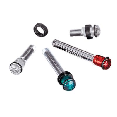
As the name implies, panel mount light pipes are those that are attached directly to the control panel or user interface.
They are attached to the panel in two ways:
- Crushable ribs that “crimp” closed
- A plastic or metal retainer ring to seal the exit surface
Board-Mount Light Pipes
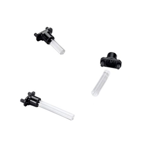
On the same end where the LED is attached to the board, the light pipe can also be attached to the PCB or surface. The LED fits inside the light pipe and is also attached to the PCB.
oard-mount light pipes can feature a rigid or right-angle design.
Rigid light pipes do not bend like their flexible counterparts.
When 90-degree angle alignment to the LED or PCB board is crucial, right-angle light pipes are mounted to the board directly over the LED. Right-angle light pipes are available in multiple board-mount options, including:
- 1-position
- 2-position
- 3-position
- 4-position
Board-mount light pipes are designed for streamlined production and assembly. The PCB board can be printed in one line, the panel in another, and then they can be machine-assembled, saving time and costs vs. manual labor.
For high-vibration applications, the panel can also be secured to a wall for additional protection.
Panel Mount / Board Mount Light Pipess
If your design includes a board- or panel-mount light pipe, you’ve got additional options to work with.
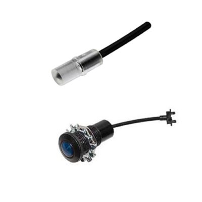
Flexible light pipes are also flexible in how they’re mounted — they work well with both panel and board mount designs. These light pipe types are ideal for devices where light needs to bend around corners and other obstacles.
An LED adapter attaches the LED and the flexible light pipe to the panel or board.
So, when you’re specifying light pipes, there are several decisions to make right off the bat. Fortunately, some of them will be made for you as other options are eliminated.
- Rigid or flexible?
- Panel mount or board mount?
- Right angle or not?
Light Pipes Work with Many LED Mounting Types
But, the decisions need to drill down even further to which types of LED mounting you will be using in your design:
Through-hole LEDs
Flexible light pipes work well with through-hole LEDs and can be mounted from the panel or the back of the device.
Right-angle through-hole LEDs
Right-angle through-hole LEDs work well with flexible light pipes that are mounted to the PC board or panel.
Surface Mount (SMD) LEDs
For LEDs that are surface mounted to the panel, flexible and rigid light pipes are options available.
Right-angle Surface Mount LEDs
Flexible right-angle light pipes that are mounted to the PC board are ideal for right-angle surface mount LEDs.
Light Pipes in Real-world Applications
Rigid LED light pipes are ideal for several industries and applications, including audio equipment, portable devices, and even mission-critical aviation equipment.
Personal Aviation Jetpack
When you’re several hundred feet in the air, there’s no time to question your aviation system’s status. See how a board-mounted light pipe solution enables clear and reliable communication day or night, even at a 140-degree viewing angle.
Portable Device Charger
Powering up to 20 devices at once requires reliable and intuitive communication. Light pipes like the LFC Series provide a soft, uniform glow and a wide viewing angle of 120 degrees for across-the-room indication.
Audio Equipment
Handmade audio equipment like mixers, preamps, compressors, and mic presses need reliable indication for adjusting levels of various inputs to create distortion and signature sound. High-intensity LEDs pair well with rigid light pipes with crushable ribs for easy, secure installation.
Flexible light pipes are perfect for transmitting light around tight corners and curves.
And their only real limitation is your imagination. Here’s a creative use of a flexible light pipe:
Smart Parking Meter
From hostile weather and the elements to vandalism, parking meters can really take a beating. But they must also reduce glare for day and night operation, especially when parking tickets are at stake. This flexible light pipe solution provides NEMA 4 and IP67 Ratings to protect from shock, vibration, and even ESD protection.
A Word About Application Environment
For light pipes that will be operated in outdoor or high-vibration environments, there are several ways to help protect and secure them for continuous reliable operation.
When light pipes will be used outdoors, they must include the appropriate level of moisture protection for their applications as well as UV stability.
Both rigid and flexible light pipes can be moisture-sealed for use in outdoor and harsh environments.
From crushable ribs and gaskets to retainer rings, there are several options to help seal in moisture and attain the IP or NEMA rating of the light pipe you need.
In addition to moisture, some applications may require shock and vibration resistance as well.
Some light pipes, like the FLXR Series litepipe, protect from all the above, and have electrostatic shock discharge (ESD) protection.
What to Consider When Choosing a Light Pipe
1. Product Design
- How many indicators are needed?
- How far apart will the power source and LED be?
- How will the light pipe be mounted?
- How far does the light need to travel? Around curves and angles?
- How much room is on board or panel?
2. Application Environment
It may seem obvious, but the environment plays a huge role in machine reliability and operation. Before landing on a light pipe, ask yourself, “Where will the device be used?”
Outdoor and High-moisture Environments
For outdoor and high-moisture environments, there are several ruggedized light pipe solutions available.
Look for products with Ingress Protection (IP) and NEMA ratings that align with your product’s needs.
Here are some examples of ruggedized light pipe solutions:
We also offer custom silicone light pipes, which provide the ideal IP and NEMA ratings to meet your design requirements.
High-Vibration Environments
For industrial and other high-vibration environments, additional hardware may be needed to secure the light pipe in place.
Flexible light pipes can be secured with either a grommet retainer or a spring retainer, depending on their length.
- Grommet retainer - for light pipes that are .250” to .500” long
- Spring retainer - for light pipes that are .500” to 1.000” long
High-vibration application in action:
Programmable Power Unit
DC power supplies demand safe and reliable operation on job sites. This low-profile, rigid light pipe solution delivered maximum brightness and minimal light loss.
Storage and Operating Temperatures
Two other key considerations for the environment of your device are the storage and operating temperatures. While the storage and operating temps will vary by device, some good rules of thumb are:
- Storage temperature – as a general rule, polycarbonate and acrylic light pipes can be stored at temperatures ranging from -100℃ to 25℃ with minimal degradation.The lower the temperature and humidity, the less degradation of the device.
- Operating temperature – this will depend on how much strain is put on the light pipe in its environment. If there is very little stress, the operating temperature can range from -100℃ to 100℃ for acrylic and -100℃ to 125℃ for polycarbonate.
Be sure to review your product’s data sheet carefully, as each light pipe will have its own properties.
3. Light Pipe Position
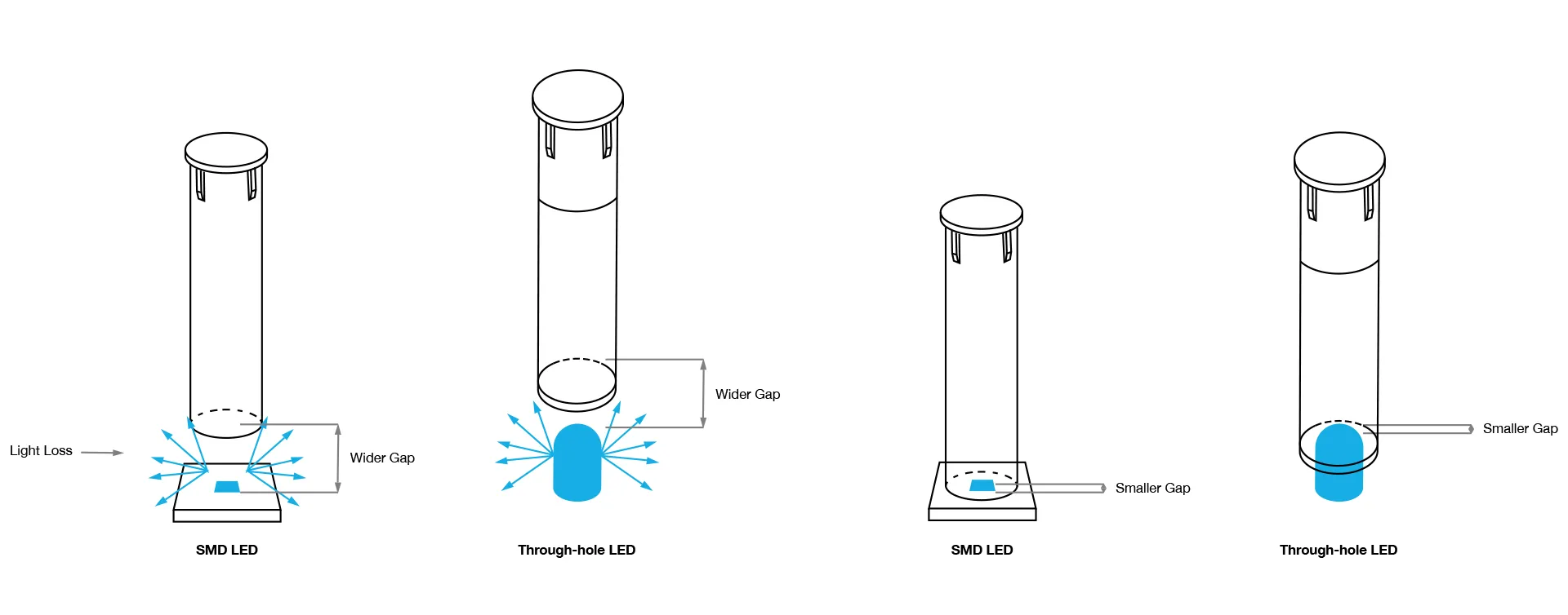
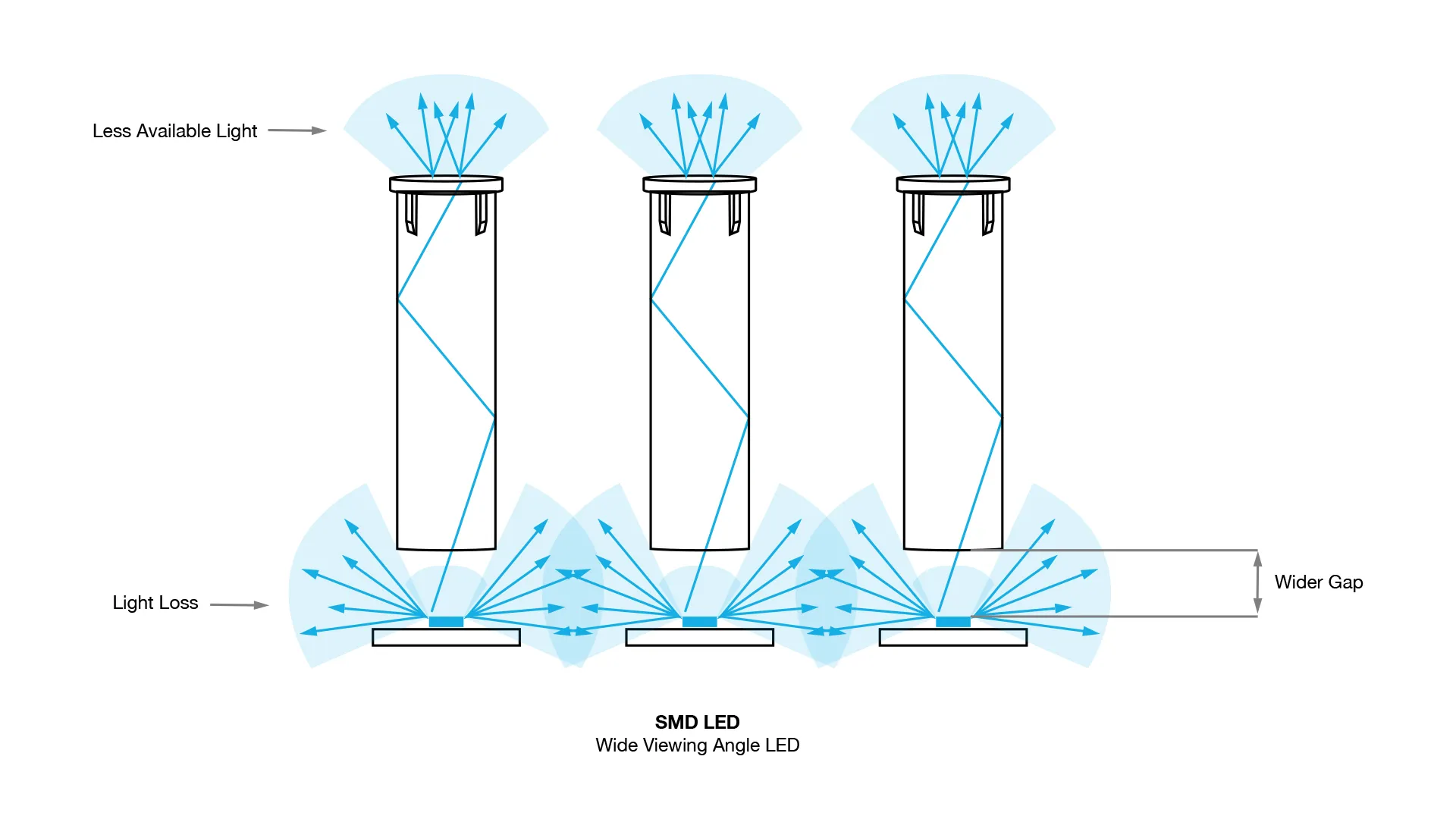
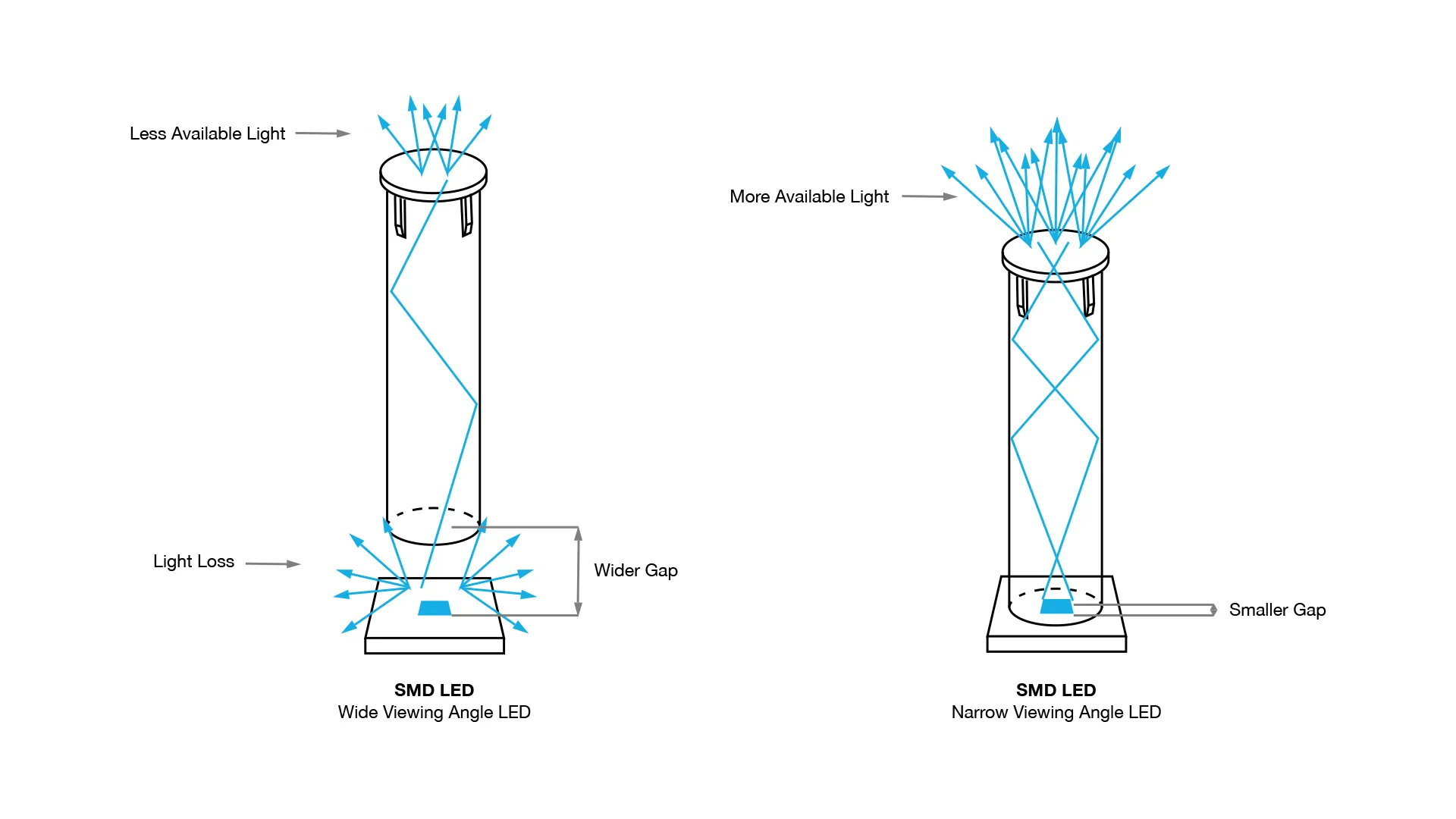
Of course, light pipe position can impact the light properties. To minimize light loss, a general rule is to use an LED with a narrow viewing angle of 160 degrees or less and position the light pipe and LED no more than 0.05” apart.
There’s a little more to it than that to get the best product for your design. That’s where light simulations come in. Contact our team to run a simulation and determine the ideal light pipe for your design.
And don’t forget the constraints you may have based on the type of light pipe you use:
Rigid light pipe design constraints
- Can’t bend
- Length limits:
-Press fit: 1.20”
-Custom: 1.5”
-Standard: up to 2” with shorter versions available
Flexible light pipe design constraints
- Bends up to 30 degrees
Light doesn’t always behave the same way, which makes light pipe design that much more complex. Why?
Let’s go back to physics class and learn about refraction.
Refraction is defined as the change in direction of a wave from one medium to another or from a gradual change in the medium itself.
So, in addition to all the other variables that go into light pipe design (size, shape, brightness, distance to LED, viewing angle, and material used, to name a few), designers must also consider the Refractive Index.
The Refractive Index is used to determine how fast light travels through a medium.
Calculated as n = c/v, c is the speed of the light, and v is the velocity of the light in that specific medium.
This number represents how much of the light is bent or refracted when it hits the medium. It also calculates how much light is reflected when reaching the medium.
In a vacuum, light breaks at a rate of 1.0. But no one designs light pipes to be used in this type of vacuum, so additional consideration must be given to optimize performance.
Plus, any number above 1.0 shows the decreased speed at which it travels compared to in a vacuum.
Sample Refractive Indices:
- In air, the rate is 1.003
- In water, the rate is 1.33
- And in acrylic — which is what most light pipes are made of — it’s ~1.49.
Yet, the Refractive Index isn’t the only number that needs to come into play when it comes to how a surface affects light.
There’s also total internal reflection (TIR), which is the angle at which light is reflected when none of it shines through to a surface exit. Instead, it is reflected from one surface to another where it is visible.
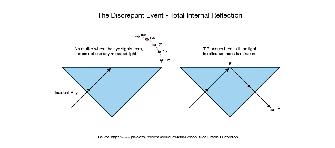

For clear polycarbonate, the critical angle is 39, and for acrylic, it’s 42.
Understanding how the light reacts in different scenarios will lead to better, more optimized light pipe performance.
For example, when using a right-angle light pipe, here’s how TIR would affect the specifications:
When designing light pipes, most people assume light behaves like electric current and ignore TIR.
Because light has unique properties, designing a light pipe like the right-angle illustration shown above will result in significant light loss at the TIR. To avoid light loss, incorporate the critical angle to create a geometry to guide the light around the critical angle without having the light escape. This concept also applies to light pipes with round corners (or any geometry your design includes).

Good, Bad, and Ugly: Light Pipes Are Everywhere
Devices with good light pipe design have the following traits:
- Uniform illumination
- No hotspots
- Ideal visibility for application
Devices with less-than-ideal light pipe designs yield bad/ugly results:
- Hot spots
- Light loss
- Difficult to see in the operating environment
Even with all of the design options available in standard flexible and rigid light pipes, there’s still plenty of need for a custom light pipe solution. Having a custom light pipe designed for your application may seem expensive, but you may be surprised at how affordable a custom design can be, often ranging from $3,000 to $15,000 (not including tooling costs).
Before you enlist the help of an engineer for a custom light pipe, you’ll need an idea of the following:
- Number of colors needed in LED
- Number of indicators on device
- Specifics on working environment
- Desired illumination intensity
- Desired viewing angle
- How far away the light indicator needs to be viewed
- Do you need help with design and production, or just design?
- Estimated annual usage of device (EAU)
- Budget and timing
- Access to design files and lighting specs (existing designs only)
To ensure your light pipe is the perfect fit for the application, environment, and device, our engineering team is made up of seasoned professionals across multiple disciplines, including:
- Mechanical engineering
- Optical engineering
- Electrical engineering
- By combining design know-how with state-of-the-art technology, VCC can easily develop a custom light pipe that meets or exceeds your optical and design requirements.
VCC’s custom light pipe services can optimize your design while reducing costs and maximizing efficiencies. Here’s how the design process works:
Step 1: Engineering Drawing
A team of engineers collaborates with OEMs and designers to establish goals and optical requirements. VCC works closely with you to prepare detailed drawings, parts lists, and circuit schematics.
Step 2: Light Simulation
VCC offers a full suite of custom light pipe design and testing services. Using the latest light modeling software, our team can run light simulations, such as ray tracing, to track the path of light through the light pipe to devise the right solution. The design is then revised and optimized until the ideal optical requirements are met.
Step 3: Light Pipe Prototype
VCC helps you cut development times using rapid prototyping techniques for plastic components. We use a 3D printer to prototype the light pipe and further test it prior to tooling the custom solution, ensuring the optimal viewing angle and lighting properties are achieved.
Step 4: Tooling & Production
When the light pipe prototype is approved, it’s time to move into tooling. Because the 3D prototype we provide is 90% accurate to the finished product, you can feel confident investing in the tooling after you’ve validated the design. Once tooling is complete, we fabricate and assemble our components in our state-of-the-art facility in Mexico, ensuring you receive the utmost level of quality, plus the many advantages nearshore manufacturing provides.
The whole process can take as little as 2 weeks or as long as 12 — it all depends on the complexity of the design.
Over the last few years, 3D printing has changed the game in light pipe prototyping, allowing some manufacturers to use in-house printers to dramatically reduce production times. Shaving days or weeks off of a timeline is a huge benefit for designers and OEMs, but 3D printing can also provide a less common advantage: completing small light pipe runs to be used in actual products.
VCC’s in-house 3D printer can print light pipes using photopolymer resin with different additives then hand polish them for use in products. These in-house printed pipes can match approximately 82-95% of the light characteristics delivered by going the injection molding route. In this case, doing a small pilot run could give OEMs and designers the quantity they need to verify the concept of their final product.
In this case, doing a small pilot run could give OEMs and designers the quantity they need to verify the concept of their final product.
For example, even complex custom light pipe concepts like this non-surgical medical device can be validated quickly and efficiently with our in-house 3D printing capabilities.
A well-designed human-machine interface (HMI) can deliver faster throughput and reduced downtime. Custom, flexible — and even rigid — light pipes open up a wide range of design possibilities by providing greater flexibility and control.
Making indicator decisions early on in the design process can help you maximize efficiencies and get exactly what you want in the finished design. This includes visibility of status indicators from distances that help the end user maintain safe and reliable operation.
To learn more, check out the VCC’s custom light pipe solutions or explore our robust light pipe portfolio.


