
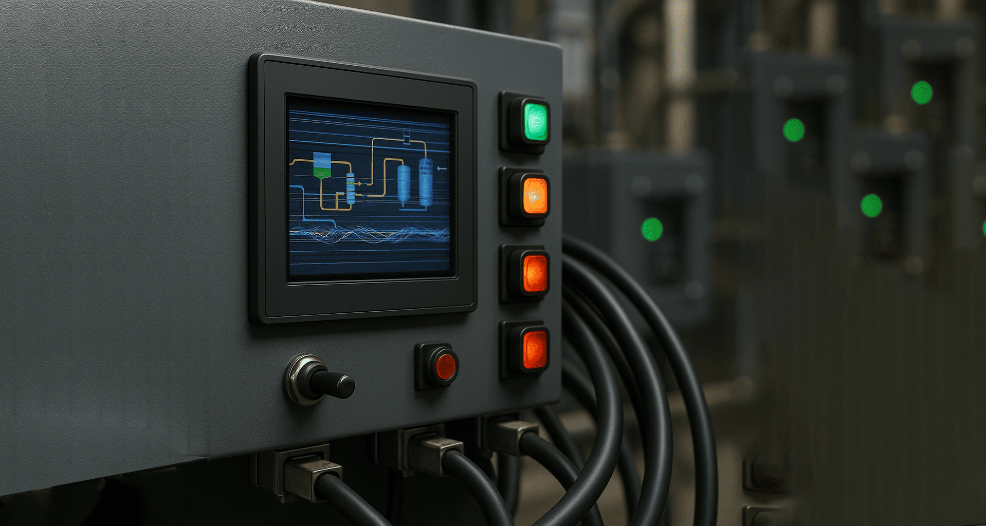
Designers meticulously plan high-speed PCBs, yet often overlook the front-facing Human-Machine Interface (HMI). This critical interface, comprising displays, switches, and interconnecting cables, is usually the primary source and receptor of Electromagnetic Interference (EMI). An electrically neglected HMI can undo all the work done on the main board.
This guide provides a practical, component-level, and system-level look at how strategic design choices for switch selection, panel layout, and physical geometry are critical for mitigating EMI and maintaining Signal Integrity (SI) in sensitive HMI systems.
The HMI creates a uniquely challenging electrical environment by combining two conflicting domains:
1. High-Frequency Components: Displays and their high-speed data cables (like LVDS or MIPI) are active sources of EMI noise.
2. Low-Frequency, Noisy Inputs: Switches and buttons, which introduce either transient electrical events or are highly susceptible to ambient noise.
When these domains interact poorly, the result is system failure.
Common HMI Failure Modes from Poor Electrical Design:
● "Phantom Touches" on capacitive screens due to coupled noise.
● Display Flicker or visual glitches caused by EMI disrupting display timing.
● Unreliable Switch Actuation or false positives, often due to switch bounce noise or external noise ingress.
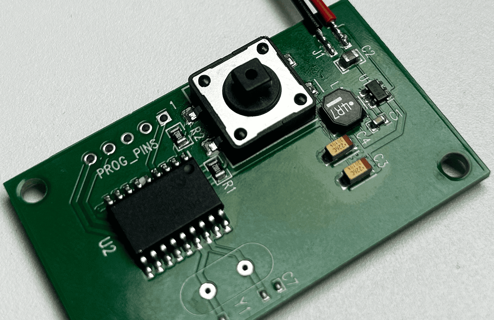
Effective EMI mitigation begins at the component level. Designers must consider the electrical profile of input devices, not just their user experience.
|
Technology |
EMI/SI Profile |
Key Design Mitigation |
|
Mechanical Switches |
Physical contact creates switch bounce, generating a transient, high-frequency noise signature that can radiate or couple into nearby traces. |
Requires a robust, time-delayed Debounce Filter (hardware or software). |
|
Capacitive Switches |
They inherently act as antennas, susceptible to coupling noise from display power lines or the external environment. |
Demands careful grounding and an isolated sensor design to reject Common Mode Noise. |
|
Hall-Effect Switches |
Offers a noise-immunity advantage, as they use magnetism rather than physical contact, but still require careful PCB layout. |
Excellent choice when looking for higher immunity to electrical noise and transients. |
Practical Circuit-Level Solutions
1. Debounce Filtering: For mechanical switches, implement a proper RC filter in hardware and/or a validated software debounce routine to eliminate the spurious signals generated during contact closure.
2. ESD Protection Design: User accessible inputs are prime entry points for Electrostatic Discharge (ESD). ESD Protection components, such as TVS diodes and ferrite beads, must be placed immediately adjacent to the physical input connector on the PCB. This ensures the ESD event is shunted to ground before the transient energy can reach sensitive input pins or propagate across the board.
The HMI Panel layout and physical geometry are vital, low-cost tools for preventing EMI coupling.
Strategic Component Spacing and Segregation
Design rules for optimal Component Spacing prevent crosstalk:
● Relative Spacing: Maintain maximum physical separation between noise-generating display ribbon cables, high-current power cables, and sensitive, low-speed switch harnesses.
● Physical Segregation: Use the HMI's frame or housing to physically separate noisy digital domains (display drivers) from analog or low-speed domains (switch wiring).
Grounding the Front Panel
A firm, unified ground reference is fundamental for practical EMI Shielding Design:
● Clean Ground Reference: Ensure the entire HMI assembly has a single, low-impedance connection to the main system ground.
● Ground Plane Stitching: If the front panel is metal, ensure a clean electrical connection to the main enclosure or chassis ground. If using plastic, apply a conductive coating and ensure it's stitched to the ground reference.
Cabling & Connectors: Interface Integration
The mechanical-to-electrical interface is a common weak point for EMI ingress and egress.
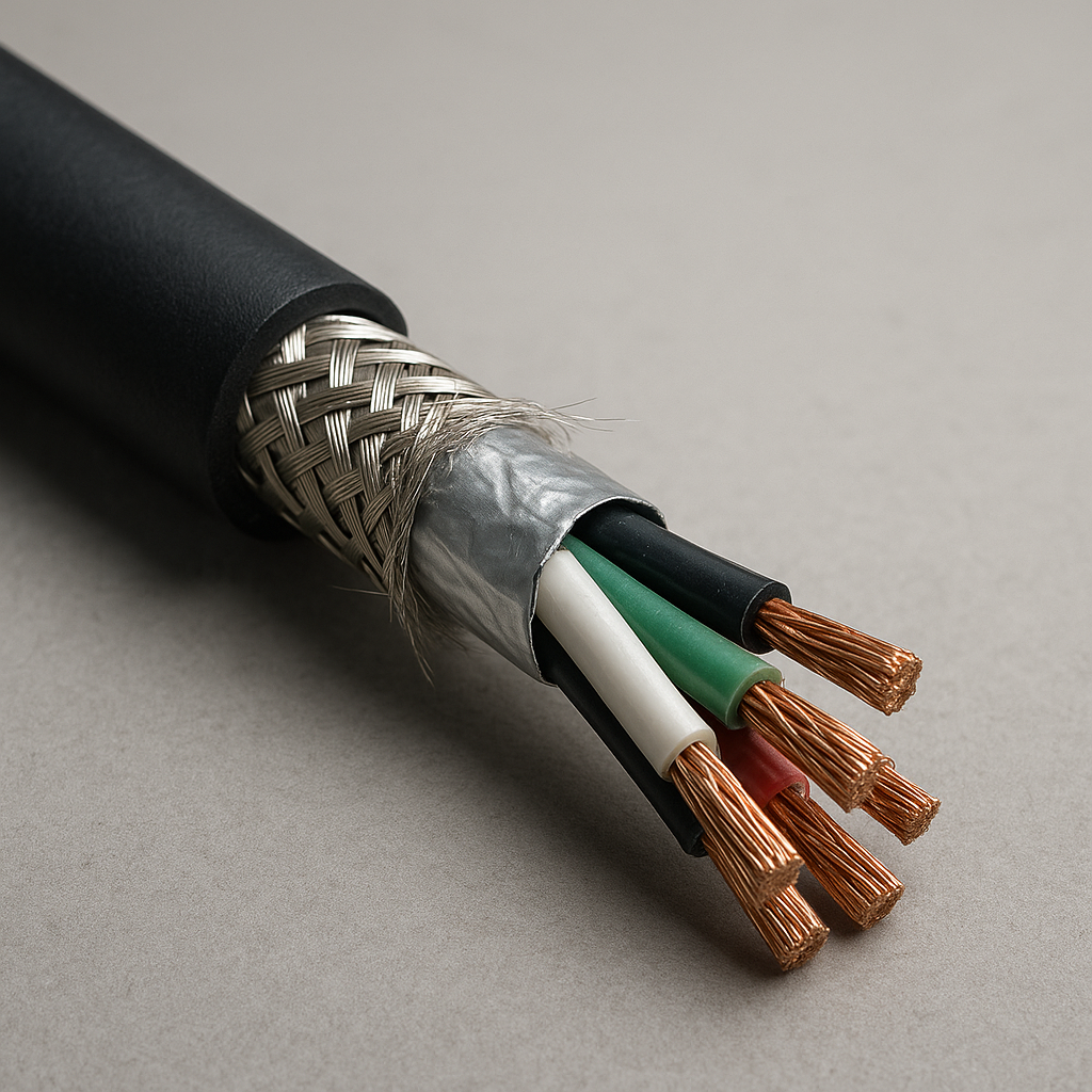
The Dangers of Unshielded Harnesses
Long, unshielded cables connecting switches or potentiometers act as highly efficient antennas, capable of both receiving external EMI and radiating internal system noise.
The Dangers of Unshielded Harnesses
Long, unshielded cables connecting switches or potentiometers act as highly efficient antennas, capable of both receiving external EMI and radiating internal system noise.
Best Practices for Cabling & Routing
● Shielded Cables: For HMI harnesses running longer distances (e.g., to remote switches), use shielded or twisted-pair cables. The shield should be appropriately terminated and grounded at the main PCB.
● Routing Advice: Avoid routing switch/control cables in parallel runs with power lines. Never route cables near high-current magnetic sources or transformers. Use smooth curves instead of sharp bends, which can compromise cable shield integrity.
● Connector Selection: Select connectors with integrated shielding or grounding capabilities. Metal-shelled D-Sub connectors or specific shielded ribbon cable connectors can prevent EMI ingress at the critical interface point.
Applying Shielding Materials to the HMI
EMI Shielding is a system, not just a metal box.
● Conductive Gaskets: Use these to seal seams and small gaps between the HMI panel and the main enclosure. They provide a continuous, low-impedance ground path, preventing high-frequency leakage through physical gaps.
● Conductive Coatings: For HMI bezels or covers made of plastic, applying a conductive coating can create a unified, cost-effective conductive surface that integrates with the central shielding system.
Conclusion
HMI design demands a holistic approach. It’s not enough to select quality display components; you must treat the switches, panel layout, cabling, and ESD Protection as a unified electrical system.
By applying these specific, actionable design principles—from managing switch bounce and selecting the right capacitive switch profile to ensuring proper front-panel grounding, you can proactively prevent complex EMI and SI issues, ensuring system reliability and a stable user experience in your next HMI project.


